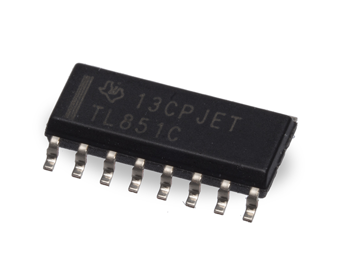
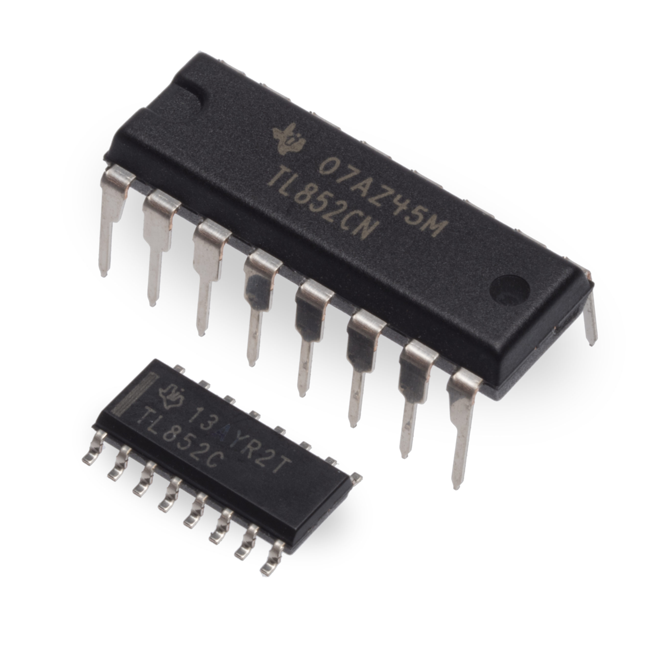
PID 614904LF – Digital IC Chip TL851CN DIP16, RoHS
$10.36 / per piece
The TL851 is an economical digital I2L ranging control integrated circuit designed for use with the SensComp TL852 sonar ranging receiver integrated circuit.
![]() Download the Specification Sheet for full details.
Download the Specification Sheet for full details.
Price Schedule
25 pcs: $10.36 ea.
100 pcs: $9.85 ea.
500 pcs: $9.64 ea.
1K pcs: Contact us for a quote…
3148 in stock
The TL851 is an economical digital I2L ranging control integrated circuit designed for use with the SensComp TL852 sonar ranging receiver integrated circuit. The TL851 is designed for distance measurement from 6 inches to 35 feet. The device has an internal oscillator that uses a low-cost external ceramic resonator. With a simple interface and a 420 kHz ceramic resonator, the device will drive a 50 kHz electrostatic transducer.
Features:
- Economical Ranging Control when used with TL852 Analog IC
- Operates With Single Supply Voltage.
- Measurement Control Range from 6 inches to 35 feet.
- Multiple Target Detection Interfaces to Electrostatic and Piezoelectric Transducers.
- Synchronous 4-bit Gain Control Output(12 steps).
- Internal 1.2 volt Level Detector.
- Accurate Clock Output For External Use.
- TTL Compatible.
The device cycle begins when initiate (INIT) is taken to the high logic level. There must be at least 5 ms rom initial power up (Vcc) to the first initiate signal in order for all the device internal latches to reset and for the ceramic resonator controlled oscillator to stabilize. The device will transmit a burst of 16 pulses each time INIT is taken high.
The oscillator output (OSC) is enabled by INIT. The oscillator frequency is the ceramic resonator frequency divided by 8.5 for the first 16 cycles (during transmit) and then the oscillator frequency changes to the ceramic resonator frequency divided by 4.5 for the remainder of the device cycle.
When used with an external 420 kHz ceramic resonator, the device internal blanking disables the receive input (REC) for 2.38 ms after initiate to exclude false receive inputs that may be caused by transducer ringing. The internal blanking feature also eliminates echoes from objects closer than 1.3 ft. from the transducer. If it is necessary to detect objects closer than 1.3 feet then the internal blanking may be shortened by taking the blanking inhibit (BINH) high, enabling the receive input. The blanking input (BLNK) may be used to disable the receive input and reset ECHO to a low logic level at any time during the device cycle for selective echo exclusion or for a multiple-echo mode of operation.
The device provides a synchronous 4-bit gain control output (12 steps) designed to control the gain of the TL852 sonar ranging receiver integrated circuit. The digital gain control waveforms are shown on page 4, with the nominal transition times from INIT listed in the Gain Control Output Table on page 3. The threshold of the internal receive level detector is 1.2 volts. The TL851 operates over a supply voltage range of 4.5 volts to 6.8 volts (+5 volts DC nominal voltage) and is characterized for operation from 0 C to 40C.

